LCSC electronics supplier MDD Shared the complete guidance about the schottky barrier diode this week. When selecting schottky barrier diodes, you could refer to this article first. We hope this helps.
Principle and Structure of Schottky Barrier Diode
Schottky barrier diode (SBD for short), also called schottky diode, is a low-power, ultra-high-speed semiconductor device for switching power supplies, inverters, drivers, and other circuits. It is used as a low-voltage, high-current rectifier diode, freewheeling diode, and protection diode, or as a rectifier diode and small-signal detection diode in microwave communication and other circuits.
Schottky Barrier Diode Principle
The Schottky barrier diode is a metal-semiconductor device made of noble metal (gold, silver, aluminum, platinum, etc.). A is the positive electrode, N-type semiconductor B is the negative electrode, and the potential barrier formed by the two touch surfaces has rectifying characteristics. Since there are many electrons in the N-type semiconductor and only a few free electrons in the noble metal, the electrons are dispersed from the high concentration B to the low concentration A. There are no holes in metal A. Thus, there is no dispersion movement of holes from A to B.
As electrons continuously disperse from B to A, the electron concentration on the surface of B gradually decreases, and damag the electrical neutrality of the surface. Thus, this forms a potential barrier, and the direction of the electric field is B→A. However, under the action of this electric field, the electrons in A will also drift from A to B, thereby weakening the electric field formed by the dispersed motion. When it creates a space charge region of a certain width, the electron drift movement caused by the electric field and the electron dispersion movement caused by different concentrations reach a relative balance, forming a schottky barrier.
The internal circuit structure of a typical schottky rectifier relies on an N-type semiconductor. On which form an N-epitaxial layer with arsenic as a dopant. The anode (barrier layer) metal material is molybdenum. It utilizes Silicon dioxide (SiO2) to eliminate the electric field in the marginal area and enhance the tube’s withstand voltage value. The N-type substrate has a small on-state resistance. And its doping concentration is 100% higher than that of the H-layer. It forms an N+ cathode layer under the substrate, whose function is to reduce the contact resistance of the cathode.
It is possible to create a suitable schottky barrier between the substrate and the anode metal by adjusting the structural parameters. When the positive bias E is applied, metal A and N-type substrate B connect to the positive and negative poles of the power supply. At the same time, the base width W0 becomes narrower. The barrier width increases when applied a negative bias voltage -E.
The schottky rectifier only uses one kind of carrier (electron) to transport charge, and there is no accumulation of an excess small number of carriers outside the potential barrier. Therefore, there is no charge storage problem (Qrr → 0), and the switching characteristics improve. Its reverse recovery time has shortened to less than 10ns. However, its reverse resistance voltage value is low, generally no more than 100V. Therefore, it is suitable for working under low voltage and high current conditions. The low-voltage drop feature can improve the power of low-voltage and high-current rectifier (or freewheeling) circuits.
Structure of Schottky Barrier Diode
The schottky barrier diode differs significantly from the PN junction diode structural principles. Its composition includes an anode metal (with a barrier layer made of materials such as molybdenum or aluminum), silicon dioxide (SiO2) as an electric field elimination material, an N- epitaxial layer (made of arsenic material), an N-type silicon substrate, an N+ cathode layer, and cathode metal. A schottky barrier diode forms between the N-type substrate and the anode metal. Applying forward bias to both ends of the schottky barrier (connecting the anode metal to the positive electrode of the power supply and the N-type substrate to the negative electrode) narrows the schottky barrier layer, reducing its internal resistance. Conversely, reverse biasing the schottky barrier widens the barrier layer and increases its internal resistance.
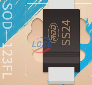
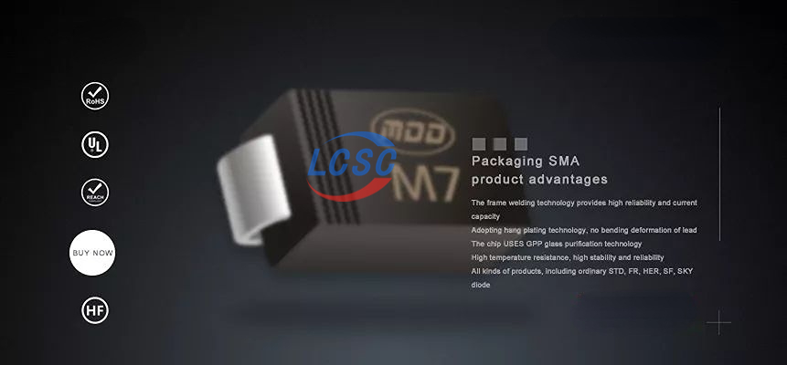
There are two schottky barrier diode packaging methods: leaded and external device (SMD). It prefers to use schottky barrier diodes in leaded packages in high-frequency and high-current rectifier diodes, freewheeling diodes, or protection diodes. It has two packaging methods: single tube type and double tube (double diode) type.
Schottky pairs of tubes have three pin-out methods: common cathode (connecting the cathodes of the two tubes), common anode (connecting the anodes of the two tubes), and series connection (the anode of one diode connects to the cathode of another diode).
Schottky barrier diodes that use external packaging include single-tube, double-tube, and triple-tube types.
About MDD Schottky Barrier Diode
“MDD” brand diodes have a complete range of varieties and specifications, including not only schottky barrier diodes but also ordinary rectifiers, fast recovery, high efficiency, ultra-fast, rectifier bridges, as well as bidirectional triggering, high voltage, transient suppression, switching, voltage stabilization and series of diode/rectifier bridges. LCSC electronics is the authorized distributor of MDD with a large selection of electronic components in stock.